
Welcome to Worldia, we have over 25 years of expertise.

How to Choose a Self Locking Connector in 2026?

Selecting a Self Locking Connector in 2026 starts with the job it must perform, not the product photograph. A connector used on a vibrating machine may need a different locking action from one used in a sheltered control cabinet. Define the signal or power requirements, contact count, operating temperature, expected mating cycles, and available space before comparing models. Small details matter. A cable that bends sharply beside the plug can place stress on the termination, even when the connector itself appears robust. Fit matters too.

Check the manufacturer’s datasheet for rated voltage and current, materials, ingress protection, and test conditions. These figures are useful only when they match your real installation. For example, a stated environmental rating does not remove the need to verify seals, cable glands, and assembly procedures as a complete system. Ask how the locking mechanism releases, whether it can be operated with gloves, and how clearly a secure connection can be confirmed. Confirm that compatible contacts, tools, and replacement parts will remain available. Then test a sample under realistic vibration, temperature, and handling conditions where practical. One missed detail can mean downtime. There is no universal best choice, and product descriptions can make comparisons seem easier than they are. This guide outlines a careful selection process, while recognizing that the final decision should follow the equipment manufacturer’s requirements and the connector supplier’s documented specifications.
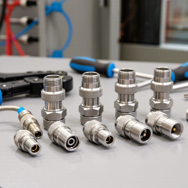
How to Choose a Self Locking Connector in 2026?

Define the Application and Operating Requirements

Start with the environment. A connector on a sheltered control panel faces different demands from one near washdown spray, dust, or constant vibration. Record the operating temperature range, moisture exposure, expected shock, and available mounting space. Be specific: a cable that bends sharply behind a machine may need more clearance than the drawing suggests.

Then define what the connection must carry. Note the working voltage, current, signal type, and number of contacts, using the equipment’s actual operating conditions rather than estimates. Include how often the connector will be mated and unmated, and whether technicians need to operate it with gloves. Small details matter. A locking collar that is awkward to reach can slow routine service, even if its retention is excellent. Also consider cable diameter, bend radius, and the direction of pull; a secure lock cannot compensate for poor strain relief.

Decide what failure would mean. A brief signal interruption may be tolerable in one setup and costly in another. This assumption deserves a second look. Check the connector’s published ratings against the real environment, and confirm that the locking method resists accidental release without requiring excessive force. If conditions are uncertain, test a sample on the actual cable and mounting arrangement. A bench test is useful, but it may not reproduce heat, vibration, or cramped access over time.

How to Choose a Self-Locking Connector in 2026?

Define the Application and Operating Requirements: start by identifying the required water-ingress protection for the installation environment.

IPX levels are distinct test categories defined by IEC 60529, not a linear measure of protection. IPX7 covers temporary immersion; IPX8 covers immersion under conditions agreed between the manufacturer and user. Select the rating that matches the actual exposure, and verify the connector’s complete IP rating and test conditions.

Compare Self-Locking Connector Types and Locking Mechanisms

Choosing a self-locking connector means comparing how it engages, releases, and resists accidental separation—not just how quickly it mates. Bayonet designs use a short turn to secure ramped pins, making connection quick when access is limited. Push-pull designs latch through straight insertion and usually release with a sleeve. Both work well for frequent mating, but their release actions differ. That matters.

Threaded couplings take longer to connect, but provide a clear, firm engagement. A locking ring or detent can help prevent loosening under vibration. Bayonet mechanisms are faster, though their pins and grooves need inspection for wear or debris. Push-pull types are convenient in tight spaces, but check whether nearby cables or equipment could press the release sleeve. No mechanism is perfect.

Match the connector to the actual conditions. Consider vibration, mating frequency, available hand clearance, cable load, and exposure to dust or moisture. Check the manufacturer’s rated mating cycles and environmental limits; a locking mechanism alone does not guarantee a sealed connection. If workers wear gloves, test the release action with gloves on. Selection charts can make the choice look simpler than it is, so a physical fit check is worthwhile before committing to a design.

How to Choose a Self Locking Connector in 2026? — Compare Self-Locking Connector Types and Locking Mechanisms
Connector type Typical locking mechanism How it engages and releases Vibration and accidental-disconnection considerations Common advantages Trade-offs and suitable applications
Threaded coupling Threaded coupling nut or shell draws the connector halves together; some designs add a secondary anti-rotation feature. Align, then rotate the coupling until fully seated. Release by unscrewing; some versions require a tool. A fully tightened threaded coupling can resist loosening, but performance depends on the design, correct assembly, and any secondary retention feature. Positive, inspectable engagement; suitable for applications requiring a secure, retained connection. Slower to connect and disconnect than many quick-connect styles. Used in industrial, instrumentation, and other applications where the selected connector’s ratings meet the requirements.
Bayonet coupling Pins or lugs travel through shaped slots and seat behind retaining surfaces, commonly after a short turn. Push the halves together and rotate to the stop. Release by reversing the turn and separating the halves. The bayonet path provides mechanical retention, but vibration resistance varies by geometry and may be improved by a separate locking feature. Fast connection with a clear, repeatable locking motion; often useful where frequent mating is expected. Requires rotational clearance and correct alignment. Check the specified cycle life, sealing, and retention ratings for the intended environment.
Push-pull locking An internal sleeve, collet, or set of locking elements engages a mating shoulder; a sliding sleeve releases the connection. Push the plug into the socket until it locks. Pull or operate the release sleeve as specified by the design to disconnect. Positive retention can reduce unintended separation, but retention and resistance to vibration are product-specific. Confirm whether release requires a deliberate sleeve action. Fast mating, often operable in confined spaces, and typically does not require a coupling rotation. Release access and cable routing matter. Suitable for frequent connection cycles when the chosen model’s electrical, mechanical, and environmental ratings are appropriate.
Snap-latch or clip-lock A resilient latch, spring clip, or locking tab snaps over a mating shoulder or into a recess. Press the halves together until the latch engages. Operate the tab or clip to release, when provided. Retention depends on latch geometry, material, wear, and assembly. A secondary lock may be used where accidental release has higher consequences. Simple, quick operation; can be compact and economical for suitable applications. Inspect for wear, damage, and complete engagement. Not every snap-fit is designed for repeated cycling, high loads, or harsh environments.
Threaded fastener or screw-lock One or more captive screws secure the connector or its shell to the mating part. Mate the connector, then tighten the retaining screw or screws. Loosen them to disconnect. Fasteners provide a deliberate mechanical hold when properly tightened. Assembly procedure and resistance to loosening under vibration should be checked for the specific design. Clear, serviceable retention; useful where a bolted connection is acceptable and accidental unplugging must be minimized. Requires access to the fasteners and adds connection time. Consider tool access, installation instructions, and inspection needs.
Magnetic self-alignment with mechanical retention Magnets help align or mate the halves; a separate latch, detent, or other mechanical feature provides retention in designs that include one. Bring the halves together for alignment and mating. Release using the designated latch or separation method. Magnetic attraction alone is not equivalent to a mechanical lock. Confirm the retention method and separation force, especially where shock or cable pull is possible. Can simplify alignment and reduce mating effort in compatible designs. Check contact design, polarity, contamination sensitivity, and whether the connector is intended for the required power or signal application.

Selection note: “Self-locking” is not a single standardized mechanism. Compare the specified retention or separation force, mating-cycle rating, vibration and shock performance, ingress protection, temperature range, current and voltage ratings, and release procedure for the exact connector design. Verify suitability against the application requirements and applicable standards.

Match Electrical, Mechanical, and Environmental Ratings

In 2026, choose a self-locking connector by matching its ratings to the actual load and installation. Check rated voltage and continuous current together; current capacity can fall as ambient temperature rises or multiple contacts operate side by side. Review contact resistance and temperature-rise test results, not just headline ratings. A connector that fits the circuit on paper may still run hot inside a sealed enclosure.

Then check latch retention, mating durability, vibration resistance, and the cable’s strain relief. IEC 60512 describes test methods for connector mechanical and electrical performance, including endurance and vibration. For exposure, IEC 60529 defines IP protection levels: IPX7 covers temporary immersion at up to 1 metre for 30 minutes. That does not automatically mean resistance to high-pressure water jets. Match the test to the real hazard, such as washdown, dust, salt spray, or repeated temperature swings. Fit matters, too. A careful bench check with the actual cable and mounting panel can reveal awkward release access or a latch that feels secure but is not fully engaged. Datasheets rarely capture every installation detail.

Check Materials, Standards, and 2026 Compliance Needs

A self-locking connector should be selected for its actual load, not its appearance. Check the latch geometry, mating force, and retention rating against vibration and cable strain in service. A convincing click helps, but it is not proof. Request test data for insertion cycles, contact resistance, and temperature rise.

Material choices shape reliability. Copper-alloy contacts conduct well; suitable plating can limit corrosion, while stainless steel may suit exposed locking parts. Match housing polymers to heat, oils, UV, and cleaning agents. Then check applicable standards for the connector’s end use, voltage, and installation. IEC or UL requirements may apply, but the exact scope matters.

For 2026 purchasing, confirm the latest editions, market-specific conformity documents, and material declarations, including restricted-substance records where required. Ask suppliers for traceable reports, not just a logo on a datasheet. Paperwork can look complete and still miss the installed configuration. I would also test a sample with the real cable and enclosure; that step is easy to overlook.

Verify Fit, Maintenance, and Supplier Support

How to Choose a Self Locking Connector in 2026?
Verify Fit, Maintenance, and Supplier Support

A self-locking connector is useful only when it fits the cable, panel, and operating conditions. Check contact count, wire gauge, voltage and current ratings, and mating dimensions against your equipment drawings. Confirm how the lock releases and whether it is practical to operate with gloves. A snug bench fit can still fail in a vibrating enclosure. Test a sample in the actual assembly before approving a larger order.

Tips: Inspect connectors after repeated mating cycles. Look for bent contacts, cracked seals, loose backshells, or a latch that no longer clicks firmly. Follow the supplier’s cleaning and lubrication instructions. Extra lubricant may attract dust. Small details matter.

Ask suppliers for current drawings, temperature data, mating-cycle limits, and clear maintenance guidance. Check whether replacement contacts and seals are available, and how quickly technical questions receive useful answers. Request traceability documents when your process requires them. A datasheet cannot reveal every installation issue. Cable bend space is easy to overlook until the panel closes. Confirm service access, sample lead time, and support after delivery. If important details remain vague, verify them before standardizing the connector.

Hi! What is your idea today?
WORLDIA 8618618272087
Nina +86 15631662072
google-site-verification=0STkOZEvYuoDp-D40AVfMUk--CzM2AsZv24S6ISPdmk