How to Choose PCD Cutting Tools for CNC Machining?
Choosing Pcd Cutting Tools for CNC machining requires more than comparing prices or counting cutting edges. The workpiece, machine, and production target must agree. Aluminum, copper alloys, graphite, wood composites, and abrasive laminates can all benefit from PCD edges, but each material behaves differently under load. A tool that produces a bright finish on one alloy may leave built-up edge on another. Small details matter.
In a CNC workshop, I would check the material grade, wall thickness, tool diameter, spindle capacity, and programmed feed before selecting a tool. Edge geometry, rake angle, clearance, and runout often influence results more than marketing claims. PCD tools usually support long service life and clean surfaces in non-ferrous and abrasive materials. However, they are generally unsuitable for prolonged machining of ferrous alloys because of chemical wear at elevated temperatures. That limitation should never be ignored.
The wrong choice becomes visible quickly. Watch the chips.
A practical selection should begin with verified manufacturer data, then move to a controlled trial cut. Record spindle speed, feed rate, cutting depth, coolant method, edge condition, and surface roughness. A short test can reveal vibration, burr formation, or unexpected heat before full production begins. Even experienced machinists can misjudge a tool when the workholding is weak or the spindle runout is excessive. Tool life estimates also deserve skepticism. They depend on machine rigidity, material consistency, and operator practice. This guide examines those variables carefully, so readers can choose confidently while leaving room for measurement, adjustment, and honest reflection.
Understanding PCD Cutting Tools and Their CNC Machining Applications
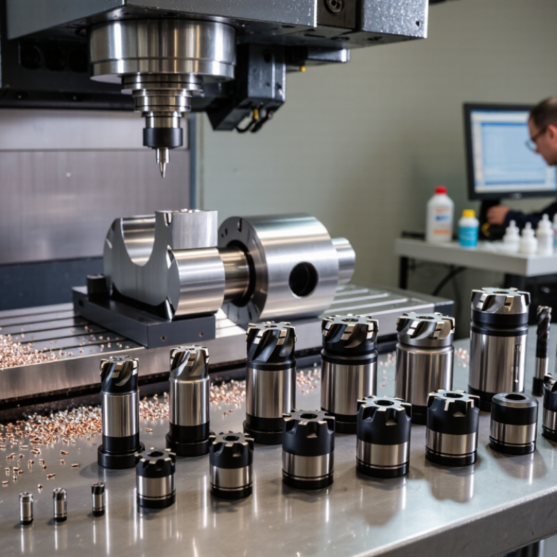
PCD cutting tools combine diamond particles with a tough carbide body. They are designed for high-speed CNC machining of abrasive nonferrous materials. Typical applications include aluminum alloys, carbon fiber composites, wood-based panels, and reinforced plastics. Their sharp cutting edges can reduce burrs and improve surface consistency. In practical shop trials, PCD tools often maintain their geometry longer than standard carbide tools. However, they are not suitable for every material. Ferrous metals can cause rapid chemical wear at high cutting temperatures. That limitation is easy to overlook.
Tips: Match the PCD grade to the workpiece. Use a fine-grain edge for delicate finishing. Choose a stronger edge for abrasive composites. Check the tool’s rake angle, corner radius, and chip clearance before ordering. Cutting speed, feed rate, and coolant conditions must work together. A reliable choice starts with actual material data, not a catalog picture.
For aluminum machining, polished flutes help prevent built-up material around the cutting edge. For carbon fiber, stable clamping reduces vibration and edge damage. In one common setup, a small corner radius produced cleaner edges, but excessive feed caused surface breakout. The first selection may still be wrong. Measure tool wear after each batch and inspect the machined surface under good lighting. This feedback improves later tool choices and protects both accuracy and production time.
Matching PCD Tool Grades with Workpiece Materials
How to Choose PCD Cutting Tools for CNC Machining?
Matching PCD Tool Grades with Workpiece Materials
PCD grade selection should begin with the workpiece, not the tool catalog. Aluminum alloys usually suit fine or medium-grain PCD. These grades produce sharp edges and clean surfaces. For abrasive aluminum-silicon alloys, coarse-grain PCD often survives longer. Check the silicon content before deciding.
Carbon-fiber-reinforced plastic demands a different approach. Its hard fibers wear cutting edges quickly, especially during high-speed routing. A finer PCD grade can reduce edge chipping and improve the laminate surface. However, excessive edge sharpness may create fragile tips. Small chamfers sometimes provide better reliability. The result can depend on fiber direction and clamping pressure.
Wood-based panels and abrasive laminates often need tougher, coarse-grain PCD grades. They tolerate dust, glue, and mineral fillers better. For a smooth decorative finish, a medium-grain grade may be more suitable. Ceramic-filled plastics can require an even more wear-resistant specification and controlled cutting speed. I have seen operators choose the hardest grade automatically. That assumption can fail. A very coarse grade may leave a rough edge on thin sheets. Trial cuts should measure flank wear, burr height, heat, and surface quality. Tool life alone is not enough. Record the spindle speed, feed per tooth, and cutting depth during testing. These details reveal whether the grade or the machining setup needs adjustment.
Selecting Tool Geometry for Cutting Performance and Surface Quality
Choosing PCD cutting tools for CNC machining starts with the workpiece, but geometry decides how that choice performs. Aluminum, carbon-fiber laminates, and abrasive composites need different edge behavior. A polished cutting edge can reduce built-up material on aluminum. Composite materials often need a controlled edge that limits fiber pullout and delamination.
Rake angle deserves careful attention. A positive rake lowers cutting forces and can improve surface quality. However, excessive rake weakens the PCD edge. I have seen sharp tools produce clean cuts briefly, then fail after a small collision or interrupted cut. Clearance angle matters too. Insufficient clearance creates rubbing, heat, and visible burn marks. Excessive clearance may reduce edge support. The best value is usually a measured compromise.
Nose radius influences feed marks and corner strength. A larger radius can improve the finish on rigid setups, but it may increase cutting pressure. On thin panels, that pressure can cause vibration or edge breakout. Keep the cutting edge polished and inspect it under magnification. Tiny chips matter. Toolpath direction also affects the result, especially near pockets and exit edges. In practice, geometry chosen from a catalog may not suit every machine. Test cuts, measured roughness, and close inspection often reveal what calculations miss. Sometimes, the first selection is simply wrong.
Evaluating Cutting Parameters, Tool Life, and Machine Compatibility
Choosing PCD cutting tools for CNC machining starts with the workpiece, not the tool catalog. PCD suits abrasive non-ferrous materials, such as aluminum alloys, copper, graphite, and some composites. Check the required surface finish and dimensional tolerance. A sharp edge can reduce burrs, but excessive sharpness may chip under vibration.
Cutting parameters directly affect tool life. Begin with the tool maker’s recommended speed range, then adjust spindle speed, feed per tooth, and cutting depth after observing the cut. High speed can improve productivity, yet heat may damage the workpiece or weaken the cutting edge. Use steady chip evacuation and suitable coolant when the material allows it. Listen carefully. A changing cutting sound often appears before visible wear. I prefer measured adjustments over sudden increases.
Machine compatibility deserves equal attention. Confirm spindle power, maximum speed, holder balance, runout, and workholding rigidity. Even a premium PCD tool performs poorly on a machine with excessive spindle runout. Inspect the cutting edge under magnification after scheduled cycles, and record wear width, burr formation, and surface roughness. Tool life is not a fixed number. It changes with material batches, clamping conditions, and operator settings. A conservative starting point may feel inefficient, but it provides safer data. My own parameter choices are sometimes too cautious, so production results should always challenge the initial plan.
How to Choose PCD Cutting Tools for CNC Machining
Representative starting values for cutting speed and planned tool life when selecting PCD tools for common non-ferrous and abrasive materials.
Higher cutting speeds are generally suitable for aluminum, copper, and wood-based panels, while CFRP and GFRP require more conservative settings to control heat, delamination, and abrasive wear. These values are engineering starting points; final parameters should be validated against spindle power, maximum RPM, workholding rigidity, coolant or air-blast capability, tool geometry, and the actual workpiece condition.