
Welcome to Worldia, we have over 25 years of expertise.

How to Choose the Right Hydraulic Couplers?

Hydraulic Couplers may look like small fittings, but their choice can affect uptime, safety, and the life of an entire hydraulic system. A coupler that fits the hose is not automatically the right one. Working pressure, flow capacity, fluid compatibility, connection style, and operating temperature all matter. So does the equipment’s daily environment: dust on a loader, vibration on a press, or repeated connection cycles in a workshop.

Fluid-power engineer John Watton’s published work focuses on how hydraulic components behave within a complete system. A practical paraphrase of that systems-based principle is: “Choose the coupler for the circuit it serves, not just the connection it makes.” That distinction is easy to overlook. A restrictive coupler can contribute to pressure loss and heat, while a poor seal may allow leaks or contamination. Small details count.

This guide explains how to compare coupler types, materials, pressure ratings, and connection methods. It also considers when flat-face designs help limit fluid loss, and why quick-release convenience should never replace checking the manufacturer’s specifications. Measure carefully. Verify the ratings. One honest limitation: no single coupler suits every machine or duty cycle. The best choice depends on the full system, including its hose, fluid, and working conditions.
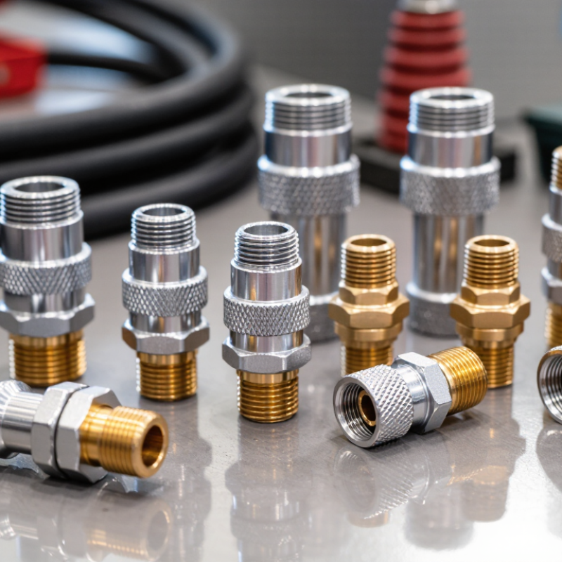
How to Choose the Right Hydraulic Couplers?

Identify the Circuit, Hydraulic Fluid, and Operating Duty

How to Choose the Right Hydraulic Couplers?

Identify the circuit before comparing coupler sizes. Check the working pressure, peak pressure, flow rate, and whether connection occurs under pressure. A pressure drop that seems minor on paper can create heat and slow an actuator. Match the coupling arrangement to the circuit: single-shutoff designs suit some lines, while double-shutoff designs limit fluid loss when disconnected. Small detail. Big consequence.

Next, confirm fluid compatibility across the coupler body, seals, and any protective caps. Check the fluid’s chemistry, viscosity, and temperature range against the coupler manufacturer’s published limits. ISO 11158 classifies common hydraulic mineral oils, but that classification alone does not confirm seal compatibility. Operating duty matters too. Frequent connection cycles, pressure surges, vibration, and hose movement can wear components faster than steady service. ISO 4406:2021 gives particle-count codes; for example, code 18/16/13 corresponds to 1,300–2,500 particles of at least 4 μm(c), 320–640 of at least 6 μm(c), and 40–80 of at least 14 μm(c) per millilitre. Clean mating faces help keep contamination out. A specification sheet can still miss the real duty cycle, so verify conditions at the machine, not just in the design file.

Compare Coupler Types Against ISO 7241, ISO 16028, and ISO 5675

Choosing a hydraulic coupler starts with the interface, not its appearance. ISO 7241-1 defines two interchange series, A and B; matching the series matters because similar-looking plugs may not connect safely. ISO 16028 specifies flat-face couplers, which help limit fluid loss and contamination during connection. ISO 5675 covers couplings used with agricultural tractors and implements. These standards provide the practical reference: compare their dimensional requirements, then verify working pressure and flow against the equipment’s technical data.

A standard match is only a starting point. Check the machine’s peak pressure, expected flow, fluid type, temperature range, and connection frequency. A coupler rated for the right pressure may still restrict flow or prove awkward in a cramped service bay. Also confirm whether trapped pressure could prevent reconnection. Real operating conditions can be messier than a specification sheet suggests.

Tips: Identify the standard and series stamped on each half. Compare the manufacturer’s pressure-flow curves and sealing data; do not assume different ISO families are interchangeable. For frequent field changes, test connection effort and leakage with the actual fluid and gloves. The overlooked detail? Dirt on a flat face can still cause trouble.

How to Choose the Right Hydraulic Couplers? — Compare Coupler Types Against ISO 7241, ISO 16028, and ISO 5675

Comparison factor ISO 7241 (Series A and B) ISO 16028 ISO 5675
Typical coupling style Push-to-connect quick-action couplings with poppet valves; the applicable series and size determine the interface. Flat-face quick-action couplings designed with flush mating faces. Quick-action couplings for hydraulic systems on agricultural equipment, using the interface specified by the standard.
Standard focus Specifies dimensional and performance requirements for quick-action couplings in its applicable series. Specifies dimensions and performance requirements for flat-face couplings. Specifies dimensions and performance requirements for couplings used in agricultural hydraulic applications.
Common applications General industrial and mobile hydraulic circuits where a compatible Series A or B connection is required. Mobile machinery and other systems where reducing fluid loss and contamination during connection is important. Tractor and agricultural implement hydraulic connections, subject to the equipment’s specified interface.
Connection and disconnection Connection method depends on the coupling design and size; confirm the mating profile and operating instructions. Connects by mating the flat faces; some designs allow connection under residual pressure, but this is product-specific. Connects using the compatible agricultural coupling interface; confirm the required mating parts and operating procedure.
Fluid loss and cleanliness Valve and seal design affect spillage. Keep faces clean and use protective caps when disconnected. Flat faces help minimize spillage and make it easier to wipe the exposed faces, but do not eliminate fluid loss or contamination risk. Spillage and contamination control depend on the coupling design and maintenance; clean and cap disconnected parts.
Interchangeability Match the same series, size, and applicable standard requirements. Series A and Series B are not interchangeable with each other by default. Match the specified ISO 16028 interface and size; do not assume compatibility based on appearance alone. Match the specified ISO 5675 interface and size; verify compatibility with the machine and implement documentation.
Pressure and flow selection Maximum working pressure and flow capacity vary with size and coupling design; check the supplier’s ratings for the exact part. Pressure and flow capacity vary by size and design; also check pressure drop at the required flow rate. Pressure and flow capacity vary by size and design; check ratings against the tractor or implement requirements.
Best suited when You need a quick-action connection and the equipment specifies an ISO 7241 series and size. Low-spill disconnection and clean handling are priorities, and the system specifies an ISO 16028 connection. You are connecting agricultural equipment that specifies an ISO 5675 interface.
Before ordering Confirm series (A or B), nominal size, connection type, pressure rating, flow requirement, seal material, and fluid compatibility. Confirm nominal size, mating profile, pressure rating, flow requirement, connection conditions, seal material, and fluid compatibility. Confirm the ISO 5675 interface, nominal size, pressure and flow requirements, connection conditions, and equipment compatibility.

Selection note: An ISO reference alone does not confirm that two couplers will mate or meet your system requirements. Verify the exact series or interface, size, pressure and flow ratings, materials, and operating conditions against the equipment documentation and the coupler manufacturer’s technical data.

Match Working-Pressure and Flow Ratings; 1 MPa Equals 145 psi

A hydraulic coupler must handle the system’s real working pressure, not just its usual gauge reading. Check the machine specifications and allow for pressure spikes during starts, stops, or sudden load changes. Working pressure is not burst pressure. Keep that distinction clear. As a quick conversion, 1 MPa equals about 145 psi; for example, 20 MPa is roughly 2,900 psi. Compare ratings in the same units, and confirm that both coupler halves meet the required pressure.

Flow matters just as much. Match the coupler’s rated flow to the system’s expected flow, such as 40 L/min, and check the pressure drop at that rate. An undersized passage can restrict oil flow and create unwanted heat. Bigger is not automatically better. Also verify fluid and temperature compatibility, connection type, and the equipment maker’s specifications. In practice, a clean connection and a readable rating label make checks easier, but labels can be unclear. I still pause when units differ; a quick conversion prevents a costly guess.

Size the Coupler for Flow; Typical Pressure-Line Velocity Is 3–5 m/s

For a pressure-line coupler, size around flow rather than matching the hose by eye. A common fluid-power design target is 3–5 m/s. Use the actual flow rate and the coupler’s narrowest internal passage: velocity (m/s) ≈ 21.2 × flow (L/min) ÷ bore² (mm²). For example, 30 L/min through a 12 mm bore produces about 4.4 m/s. At 10 mm, it rises to about 6.4 m/s. That smaller passage may increase pressure loss, heat, and sluggish response. Check the coupler’s flow-versus-pressure-drop curve, not just its nominal size.

ISO 4413:2010 covers safety and design requirements for hydraulic systems; the ISO 7241 series specifies requirements and tests for quick-action couplings. These standards do not make 3–5 m/s a universal limit. Treat it as a practical sizing target, then verify the operating pressure, fluid viscosity, duty cycle, and manufacturer-neutral performance data. A pressure-line coupler can also become the bottleneck when its internal valve is smaller than the hose. Easy to miss. Measure the assembled connection where possible, and compare pressure drop at peak flow. The calculation is only a starting point; real fittings and bends add losses, and field measurements may reveal an imperfect assumption.

How to Choose the Right Hydraulic Coupler? Size the Coupler for Flow

Typical pressure-line fluid velocity is 3–5 m/s. The chart shows the corresponding flow range for each internal diameter, calculated using Q = velocity × cross-sectional area. Use the actual coupler bore for preliminary sizing, then verify pressure drop and the equipment manufacturer's flow recommendations.

Check Seal Compatibility, Connection Type, and Safe Disconnect Requirements

How to Choose the Right Hydraulic Couplers?

Seal material must suit the fluid, temperature, and pressure—not just the hose size. Mineral oil, water-glycol fluids, and synthetic oils can affect elastomers differently. Check the equipment manual and seal compatibility data before ordering. ISO 3601 provides dimensional and tolerance requirements for O-rings, while fluid compatibility still depends on the specific compound. Small details matter. A seal that swells can make connection difficult; one that hardens may leak under pressure. Compatibility charts help, but they cannot replace checking the actual fluid blend and operating temperature.

Match the connection type to the equipment and working conditions. Thread form, port size, and coupling series must all align; similar-looking threads are not necessarily interchangeable. ISO 7241 covers dimensions and performance requirements for hydraulic quick-action couplings, making it a useful reference when comparing series. Then consider disconnection: will the line be depressurized, and can trapped pressure remain on either side? OSHA safety guidance warns that fluid injection injuries can occur at pressures as low as 100 psi. Disconnect only as specified by the equipment maker, and never use a hand to search for a leak. A coupling can feel secure and still be the wrong choice. Recheck the spec sheet before installation.

Hi! What is your idea today?
WORLDIA 8618618272087
Nina +86 15631662072
google-site-verification=0STkOZEvYuoDp-D40AVfMUk--CzM2AsZv24S6ISPdmk